Tangential Rolling Systems

Tangential rolling systems

Threads of the highest surface quality can be produced with minimum machining times using the Wagner tangential rolling system.

The tangential rolling tool is mounted with the adapter on the tool carrier, e.g. turret disc. It moves with a constant feed onto the rotating workpiece. The thread rolls are set in rotation by touching the workpiece and form the thread as the tool carrier continues to feed. As soon as the thread rolls have reached the centre of the workpiece the rapid return is initiated and the workpiece is released. Optimum productivity is achieved using precise thread rolls with maximum tool life. The diameter, pitch and shape of the rolls are adapted to the thread to be rolled. Wagner tangential rolling tools are available in various sizes and are suitable for machining workpieces from Ø 1.6–52 mm.

Premium rolling results in fine-pitch threads can be achieved by using our tool variant “F”. For threads with very small pitches, it is important to keep the axial play of the thread rolls as low as possible. By means of the patented Wagner axial play fine adjustment, the axial roll play can be minimized in 0.02 mm steps. The fine adjustment is available as an option.

Profile rolls for special applications such as rolls for lubrication grooves, knurling or smoothing are also available.

AREAS OF APPLICATION

  • cylindrical and conical threads, right- and left-hand threads as well as regular and fine threads
  • threads behind a collar
  • threads close up to a collar
  • very short threads
  • threads where the end of the workpiece is not free
  • threads with very short run-outs

ADVANTAGES

  • very short processing time
  • large operating range
  • long tool life due to large rolls and high rigidity of the tool body
  • particularly low-maintenance
  • the rolled threads are suitable for high loads due to their uninterrupted fibre course direction.
  • durable, wear-resistant and corrosion resistant threads
  • high flexibility due to numerous adapter variants for use on different machines, e.g. single and multispindle lathes as well as special machines

STANDARD TYPE

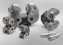
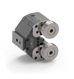
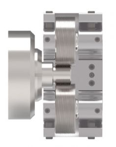
Maximum stability with large working range.

TypRegelgewinde Ø
(mm/Zoll)
Feingewinde Ø
(mm/Zoll)
Gewindelänge max. – minus 2 x Gewindesteigung
(mm)
Abstand Rolle bis Werkzeugkante (X)*
(mm)
Max. Vorschubkraft
(N)
Gewicht Werkzeug mit Rollen
(kg)
Gewicht Adapter
(kg)
B 8-W1,6–12 mm / 0,06–0,5″1,6–13 mm / 0,06–0,5″14716000,9ca. 1,5
B 10-W2–16 mm / 0,08–0,625″2–16 mm / 0,08–0,625″191025001,9ca. 1,7
B 144–22 mm / 0,157–0,875″4–35 mm / 0,157–1,375″25,513,550003,5ca. 2,0
B 166–22 mm / 0,25–0,875″6–45 mm / 0,25–1,75″25,513,557003,7ca. 2,0
B 198–27 mm / 0,3125–1″8–52 mm / 0,3125–2″3116,598007,5ca. 3,0

TANGENTIAL SYSTEMS WITH FRONT MOUNTED ROLLS

Front mounted rolls make it possible to roll threads directly up to a collar or chuck.

ADVANTAGES

  • Working range M3–M42 / UN5–40 to UN 1 5/8″
  • Problem solver for demanding workpiece geometries and special workpiece clampings
  • For highest thread quality
  • Process reliability due to high performance thread rolls
  • Simple operation and quick roll change
  • Shortest machining times
  • Ideal e.g. for stainless steel fittings
Typ Regelgewinde Ø
(mm/Zoll)
Feingewinde Ø
(mm/Zoll)
Gewindelänge max.
(minus 2 × Gewindesteigung)
(mm)
Max. Vorschubkraft
(N)
Gewicht Werkzeug mit Rollen
(kg)
Gewicht Adapter
(kg)
B13-VB 3–10 mm / 0,12–0,375″ 3–24 mm / 0,12–0,9375″ 17 4000 4,5 ca. 2,0
B16-VB 12–16 mm / 0,5–0,625″ 8–42 mm / 0,5–1,625″ 20 4000 5,4 ca. 2,0

STANDARD DESIGN

Maximum stability combined with a large working range

DESIGN WITH FRONT MOUNTED ROLLS

Tangential rolling tools with front mounted rolls are available exclusively from Wagner. Within the shortest machining times, it is possible to roll threads directly up to the collar or the chuck. These tools are designed for use on all common lathes with a controlled feed motion.

TYPE VARIANT F

Quick and easy adjustment of the AXIAL ROLL PLAY for best thread quality and long tool life for Type “F”. Especially recommended for fine threads.

GEWINDEROLLEN – TANGENTIALWERKZEUGE

ROLl FORM AND SELECTION CRITERIA

Depending on the application, different types of thread rolls can be used. The roll form DR is not possible for all threads and must be clarified for each individual case.

C1-Rolls Standard roll with full profile width with one-sided, non recessed driving slot
C2-Rolls Rolls with profile width matched to the thread length for rolling behind a collar
C3-Rolls Rolls with profile width matched to the thread length and clamping length for rolling in front of a collar
C4-Rolls Rolls with profile width matched to the thread length and clamping length for rolling behind a collar
C5-Rolls Two threads of the same dimension can be rolled simultaneously
CR1-Rolls For the production of short threads. Tool life can be doubled by turning the rolls
CR4-Rolls For the production of short threads behind the collar. Tool life can be doubled by turning the rolls
CR5-Rolls For rolling a short thread behind a narrow collar. Tool life can be doubled by turning the rolls
DR1-Rolls It should be possible to turn the rolls (double the tool life). The driving slots are recessed, as the profile width of the CR1 rolls is not sufficient.
DR5-Rolls For rolling a short thread behind a narrow collar. Double the tool life by turning the rolls. The driving slots are countersunk, as the profile width of the CR5 roll is not sufficient.
K2-Rolls For rolling a tapered thread behind the collar (tapping side)
Q2-Rolls For rolling tapered threads at the open end of the workpiece

DIMENSIONS OF THE THREAD ROLLS

The dimensions for the individual shapes of the thread rolls can be taken from the following table:
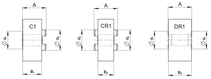
TypAB1B2B3d1d2
B814,7 mm12,2 mm10,8 mm14,2 mm12,9 mm14,4 mm
B1019,8 mm15,8 mm13,2 mm19,3 mm14,9 mm17,1 mm
B13–B1626,25 mm22,6 mm19,7 mm25,75 mm20,1 mm21,8 mm
B1935 mm31,2 mm28,5 mm34,5 mm23,3 mm25,2 mm

THREAD RUN-OUT, THREAD UNDERCUT

The thread rolls are chamfered at an angle α. For workpieces without undercut, the angle α = 30° should be used. Angle α = 45° or 60° is used when the last full thread of the workpiece must be very close to a collar and only for workpieces with undercut.

S = Sicherheitsabstand (min. 0,3 mm)
L = erforderlicher Gewindeauslauf ( = Z + S)
M = erforderlicher Überstand der Gewinderolle in den Freistich
O = erforderliche Breite des Gewindefreistichs (= M + S)

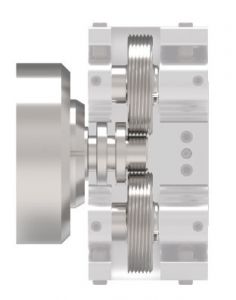
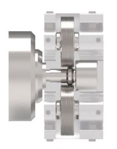
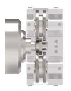
Die Gewinderollen und der Bund des Werkstückes dürfen sich nicht berühren, d.h. es muss ein Sicherheitsabstand vorgesehen werden. In den Abbildungen sind die erforderlichen Abstände dargestellt.

α = angle of the chamfer on the thread roll
Z = width of the chamfer
T = depth of the thread profile


The thread rolls and the collar of the workpiece must not touch each other, i.e. a safety distance must be provided. The required distances are shown in the illustrations.